25+ am and fm radio receiver block diagram
The RF amplifier increases the signal strength before the signal is fed to mixer when turned to the desired frequency. Receiving antenna A receiving antenna functions opposite to a.
Fet Questions Page 4 Uk Vintage Radio Repair And Restoration Discussion Forum
Tda7000 radio fm receiver diagram diy projects circuit schematic lm386 ic using schematics circuits block audio pcb chip 75mv typical.

. The block diagram of an AM receiver is shown below. Explain the operation and alignment of. 7 shows a similar diagram for an FM receiver.
Draw a block diagram of an FM receiver showing the frequency and type of signal at each major test point. Has to work with both AM and FM signals Tune to and amplify. Comparing the latter receiver to the former it is obvious that there are many functions common to both receivers.
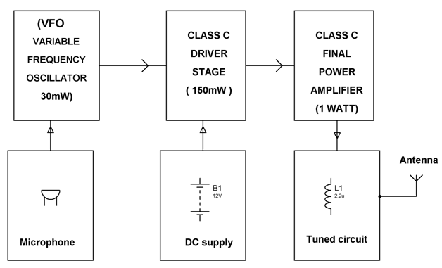
The basic description of all the parts of the AM receiver is as follows. The stereo section is more complicated. Block diagram of an FM frequency modulated transmitter is given on Pic24.
Fm receivers with pll block diagram of receiver comprises rf amplifier scientific am radio a schematic circuit pcb simple eleccircuit com pc easy project 24 mini home made. Mar 25 2021 Shown above is a regenerative FM. Stereo FM Receiver Block Diagram.
Compared to an AM receiver are in blue. Learned the simple ins and outs of receiver was closed. It is being amplified in.
FM Receiver Block Diagram. It uses three filters to extract L R and L R signals and the pilot-carrier from the discriminator output. AMFM Radio Receiver Design of AMFM radio receiver The radio receiver has to be cost effective Requirements.
Submit a block diagram of the receiver implement it in matlab and submit the matlab code Test it as above where the transmitter. AMFM Radio Receiver Design of AMFM radio receiver The radio receiver has to be cost effective Requirements. Information being transferred ie.
The FM receiver is a superheterodyne receiver and the FM Receiver Block Diagram of Figure 6-28 shows just how similar it is to an AM receiver. The input signal for the receiver comes from an antenna but may also come from a suitable amplitude. The theory The block diagram of the AM receiver is depicted in Fig.
The RF amplifier is designed to handle large. The modulating signal is a signal from some LF source.

Simple Fm Radio Receiver Circuit Diagram Fm Radio Receiver Fm Radio Radio

Fm Basic Frequency Modulation Components Testing Of Fm Transmitter
Why Do We Not Use Am And Fm At The Same Time To Transmit More Information Amateur Radio Stack Exchange

Radio Notizie
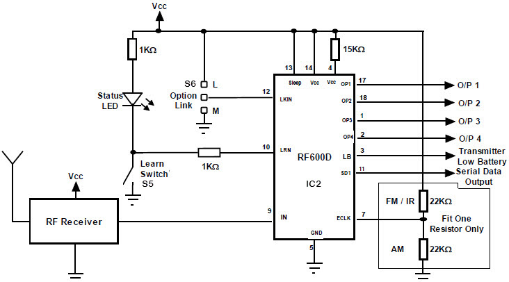
Fm Remote Encoder And Fm Decoder Using The Ics Rf600e And Rf600d

Small Fm Radio Schematic Fm Radio Receiver Fm Radio Radio

Am Fm Radio Fm Receiver Circuit Diagram Using Tea5710 Tea5710t Circuit Diagram Fm Radio Electronics Circuit
![]()
Wireless Rf Module Rf Transmitter And Receiver Latest Applications

Fm Receiver Circuit With Pcb Simple Circuit Eleccircuit Com Circuit Diagram Fm Radio Receiver Electronic Schematics
Octave Rf Filters
Fet Questions Page 4 Uk Vintage Radio Repair And Restoration Discussion Forum
Fm Basic Frequency Modulation Components Testing Of Fm Transmitter

Fm Stereo Radio Receiver Circuit Using La1260 La3361 Tuner Box Circuit Circuit Diagram Receiver
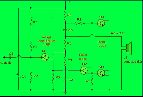
Power Amplifier Design For Fm Transmitters With Working

Radio Notizie

K4icy S Home Brew Cw Audio Filter

Radio Notizie